how do attenuverters work?
attenuverters are useful little devices, and i learned a lot from looking at the circuit.
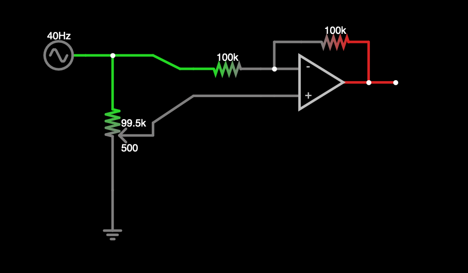
here is a simple one:
(this is one from https://kassu2000.blogspot.com/2018/04/precision-attenuverter-mixer.html?m=1)
in the middle of the range, the potentiometer looks like a pair of 50k R. if we turn it fully inverted, or at least as far as the sim will let us, it looks like a 99.5k and a 500R:
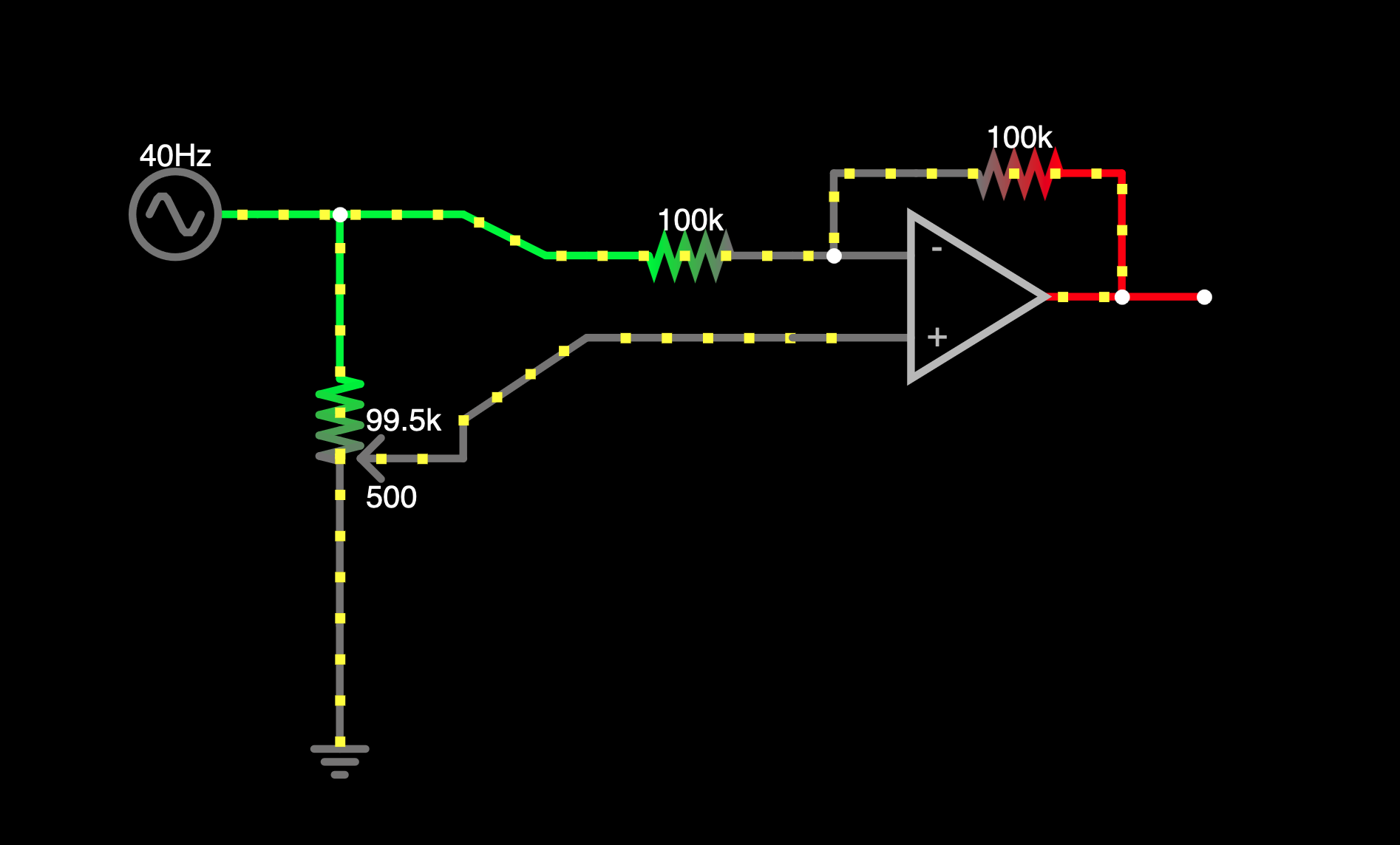
if we could turn it the whole way, it would look like a 100k R and a wire, and its sort of easier to understand what is happening if we just pull the pot out of the circuit and replace it with that:
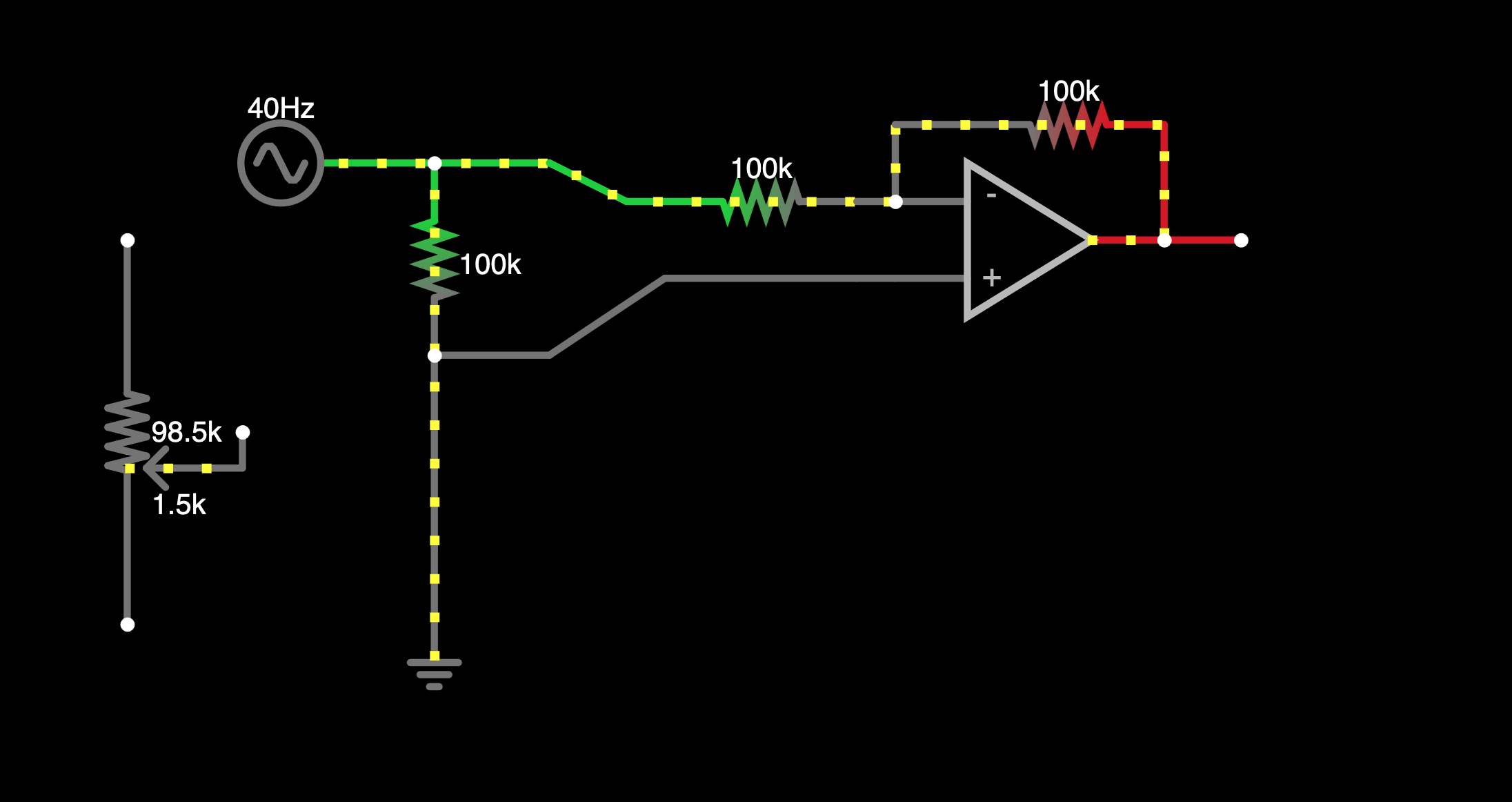
this ^^ is the same as:
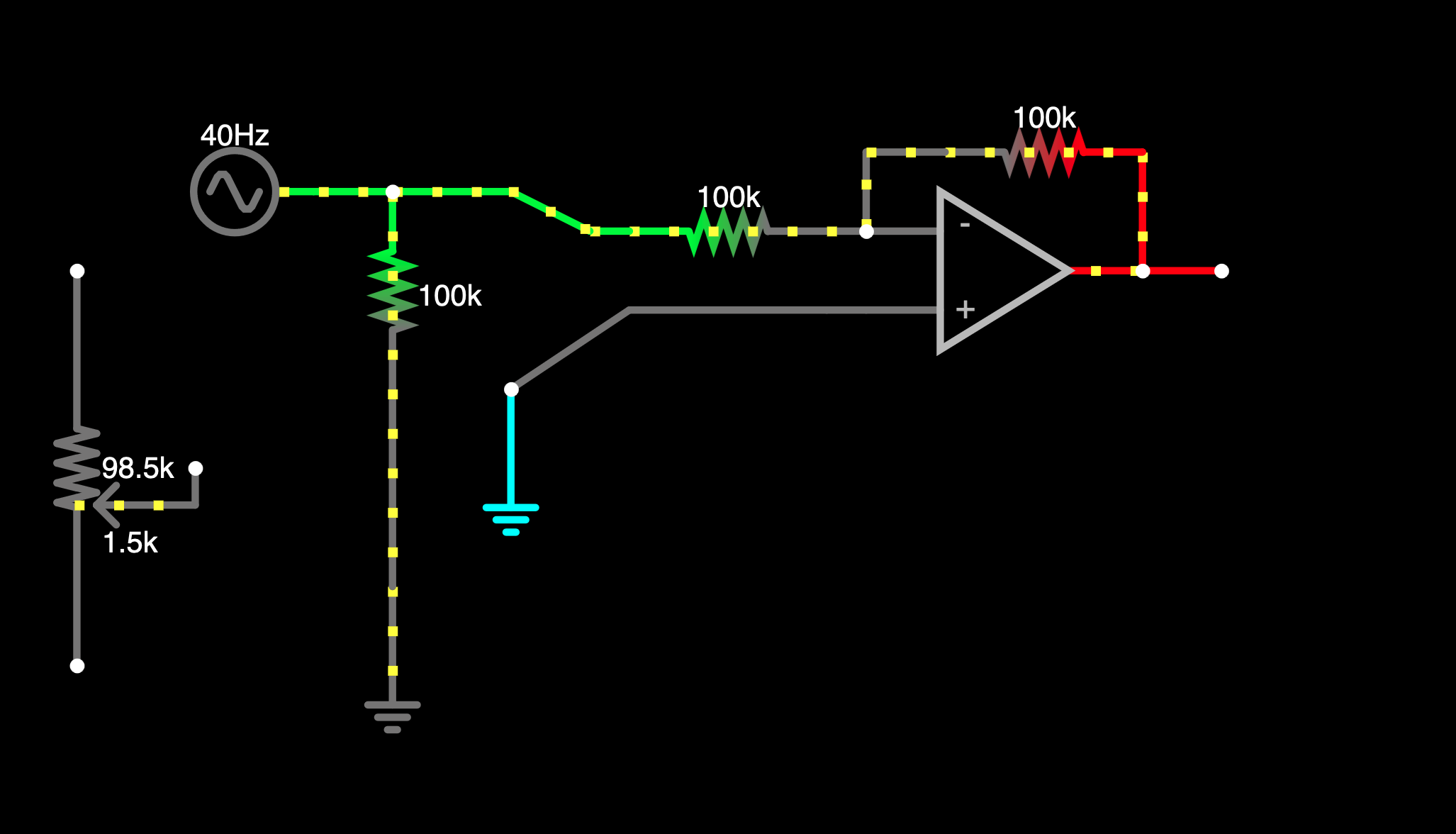 ... which is a pretty straightforward circuit, it looks like a basic inverting opamp configured for -unity gain. the only thing extra is that right after the source we have that wire going south through the 100k R to ground. is this doing anything? not really, or not in context of the opamp; its just shuttling some current to (and from) ground (we'll leave it here for now, but come back to it later when talking about what R values to use).
so this is pretty understandable - when the pot is all the way to the inverted side, it's kind of like we short the opamp's positive terminal to ground, and the circuit looks a lot like a regular inverting buffer.
what about when the pot is turned to the other end? we can model this by swapping where the 100k R and the wire are, like this:
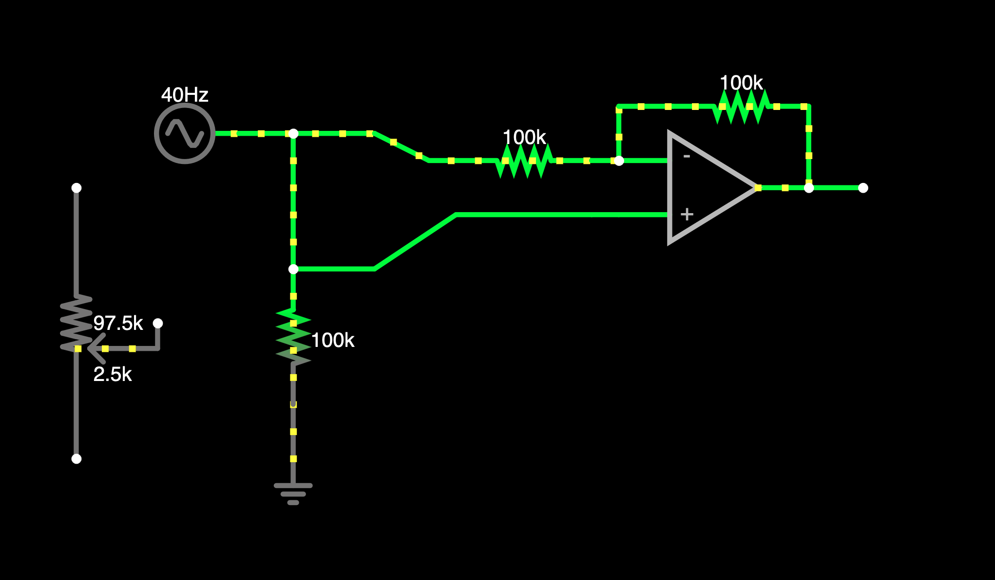
so what is happening? below is the circuit snapshotted at the low end of the oscillating input; the positive opamp input is at -5V, and so is the output, so it is doing what an attenuverter should, but the circuit doesn't look anything like a non-inverting amplifier, so how does it work?
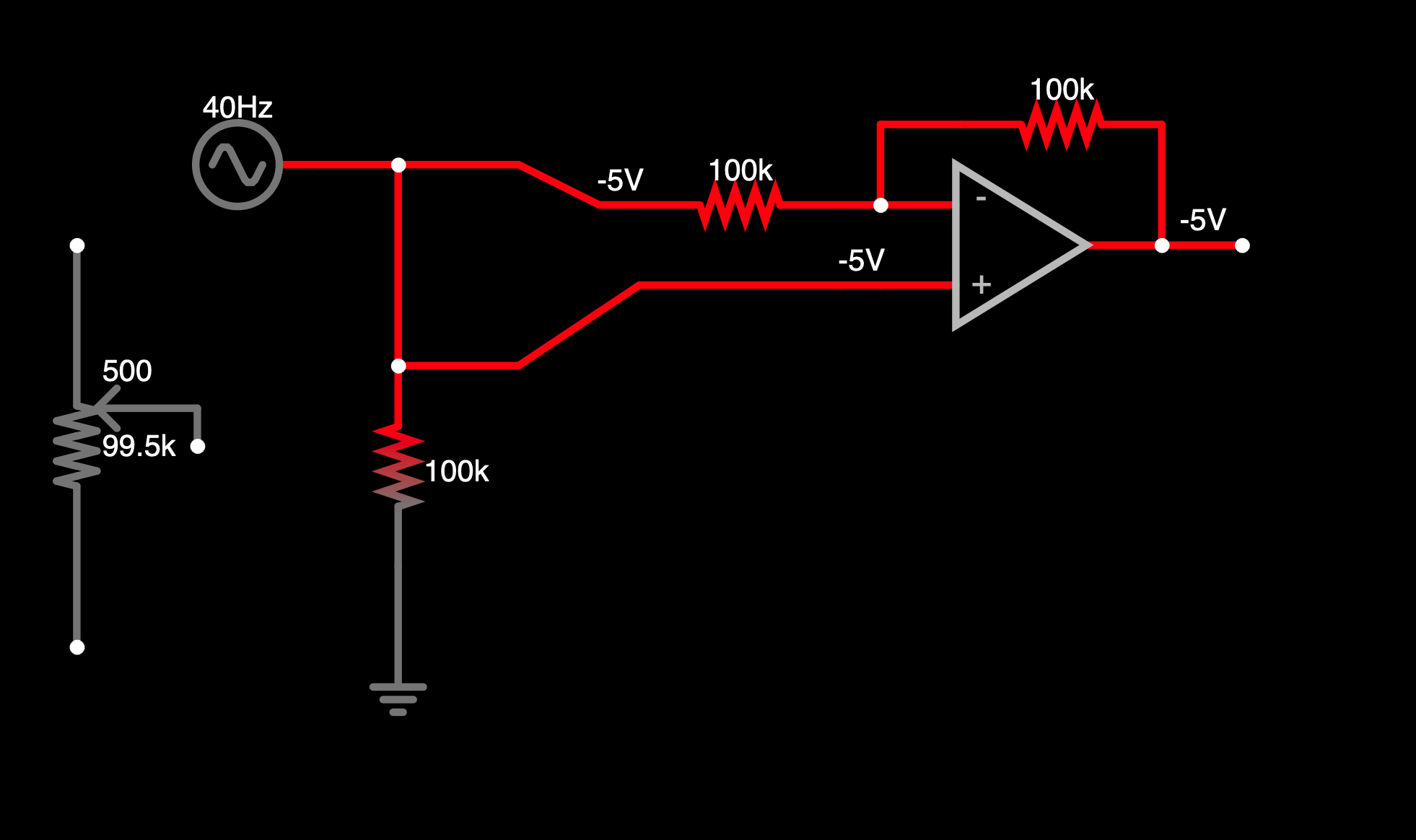
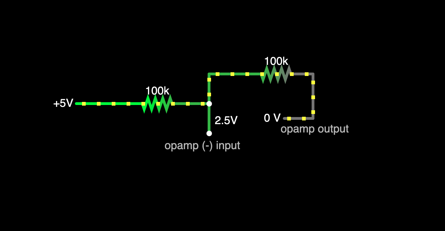
if we look at just the opamp feedback network by itself, it looks like this:
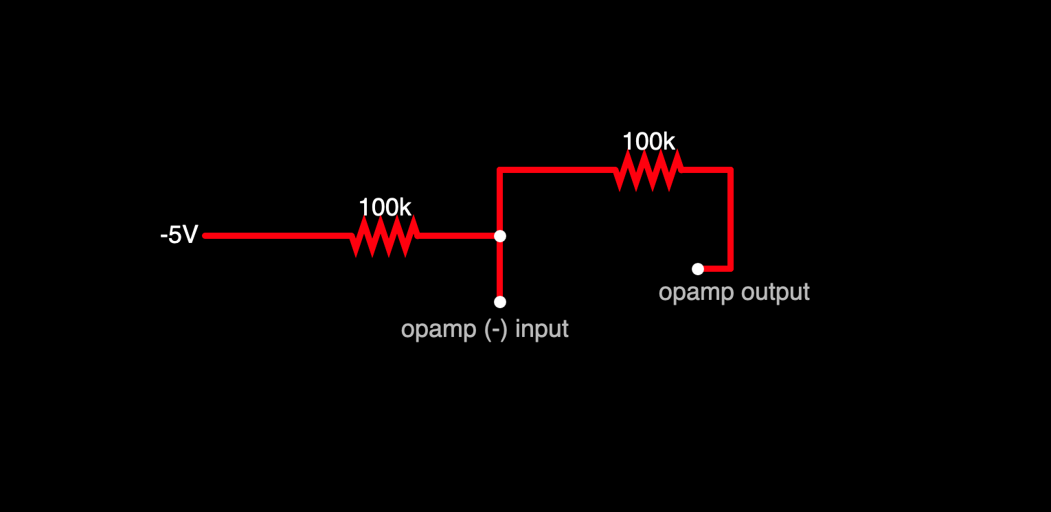 ... we know that the (+) opamp input is at -5V, so we know also that the opamp wants to make the (-) input also be at -5V. if there were no feedback resistor, it wouldn't have any work to do, because both nodes are already at -5V. but there is the feedback network, and this is where it is sort of interesting. because if the opamp pushes 0V from the output through the feedback, the result is not -5V at the inverting input, but rather -2.5V:
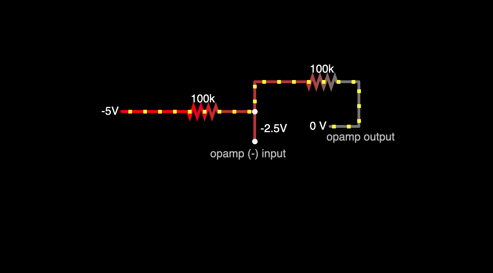 this ^^ looks very much like a voltage divider - for example, if we clean it up, straighten some wires, and replace the 0V source with ground:
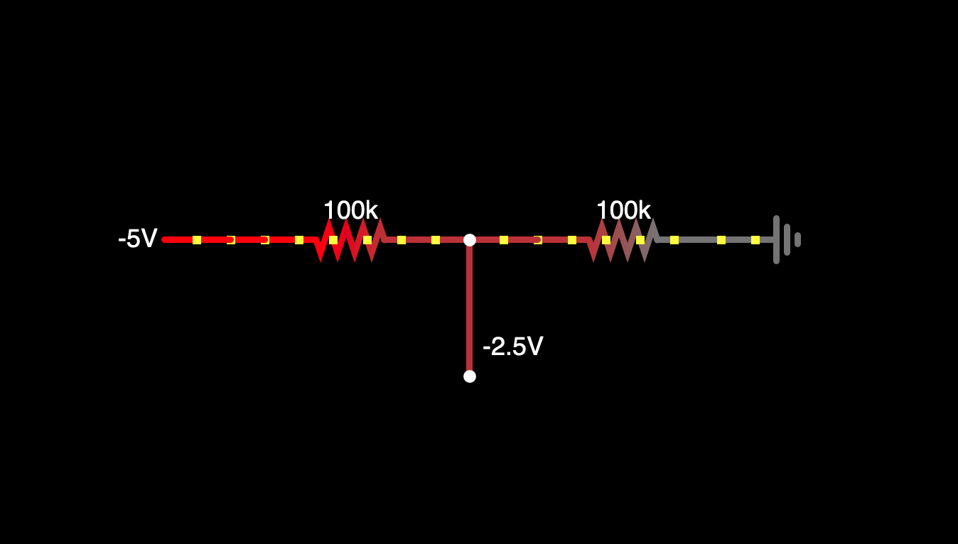
what happens to this if we don't use ground at the right end? say we give it -2V instead:
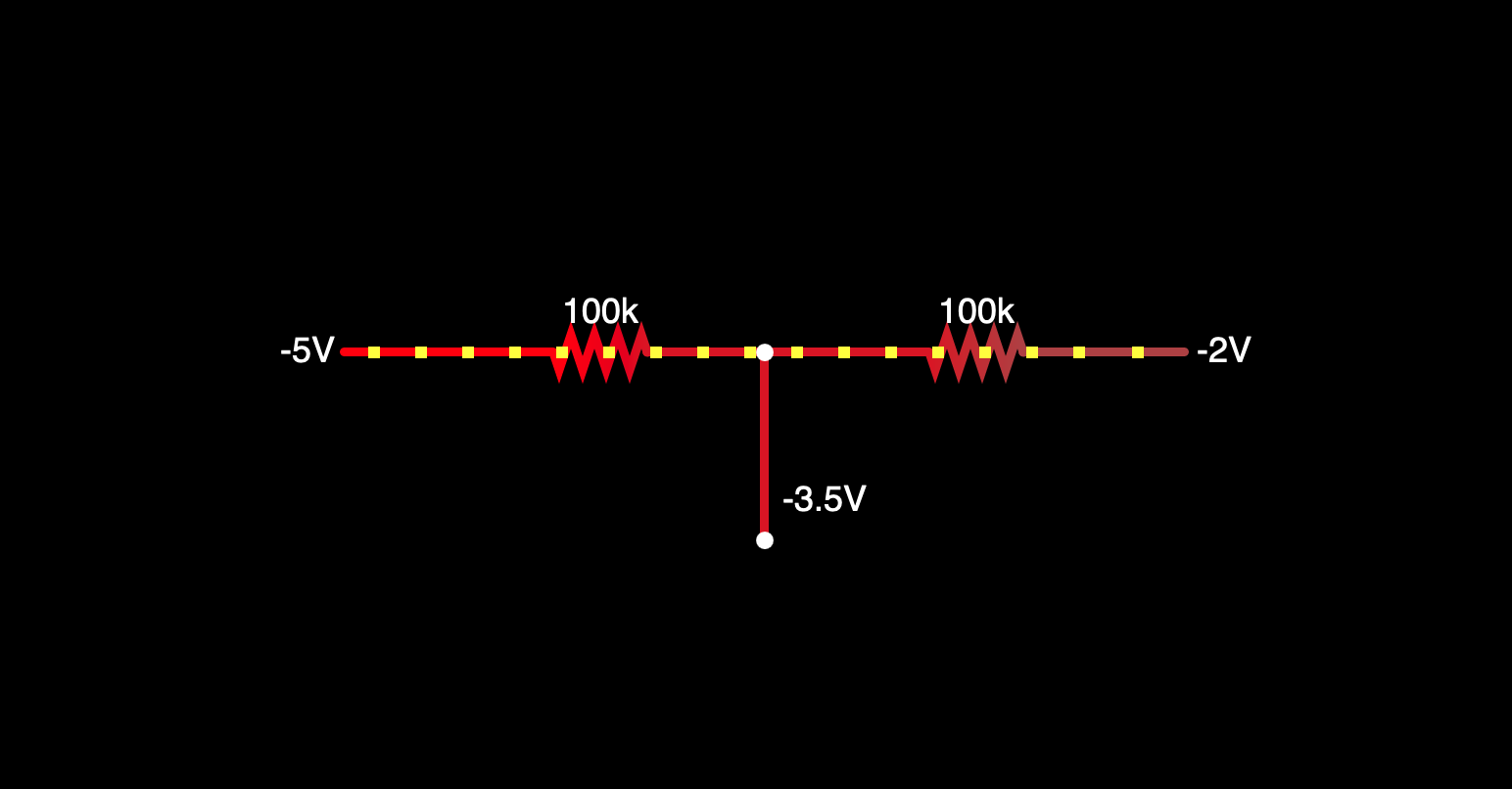 ... it is -3.5, the average of the two. so that's kind of interesting. so it is really only a divider if one of the sources is ground, otherwise it is an averager(?)
so if it is an averager, and it has -5V at one end, -5V is the desired output in the middle, then we have to have -5V at the other end:
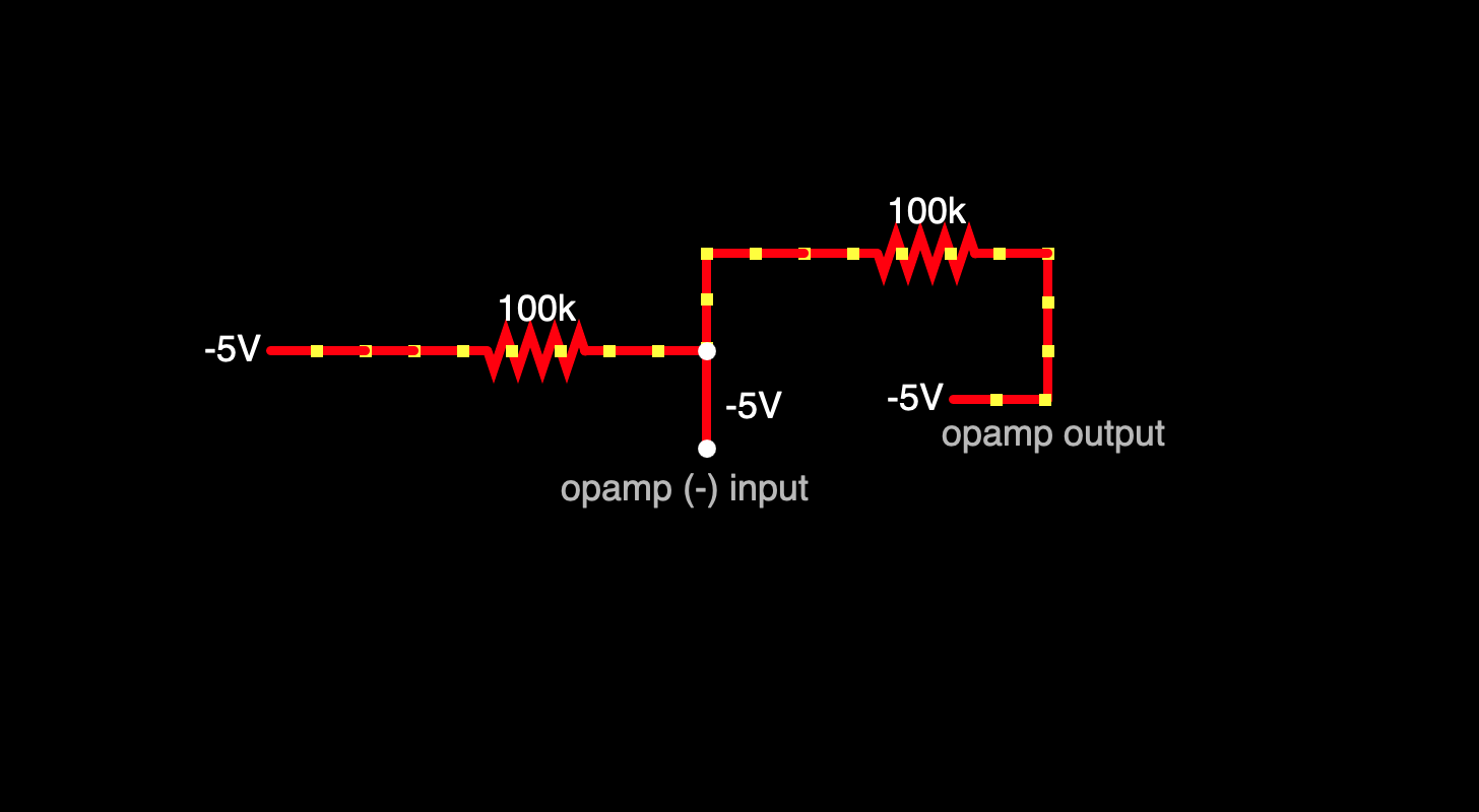 ... and this ^^ is why the opamp has to push -5V from the output. and when the input signal - the oscillator - is at any other point, the system works the same way - so if the oscillator is at its peak at +5V, then the opamp has to push +5V.
that explains what the circuit looks like when the pot is at either end; what does it look like when it is in the middle? shown here, when the oscillator input is at its peak of +5V:
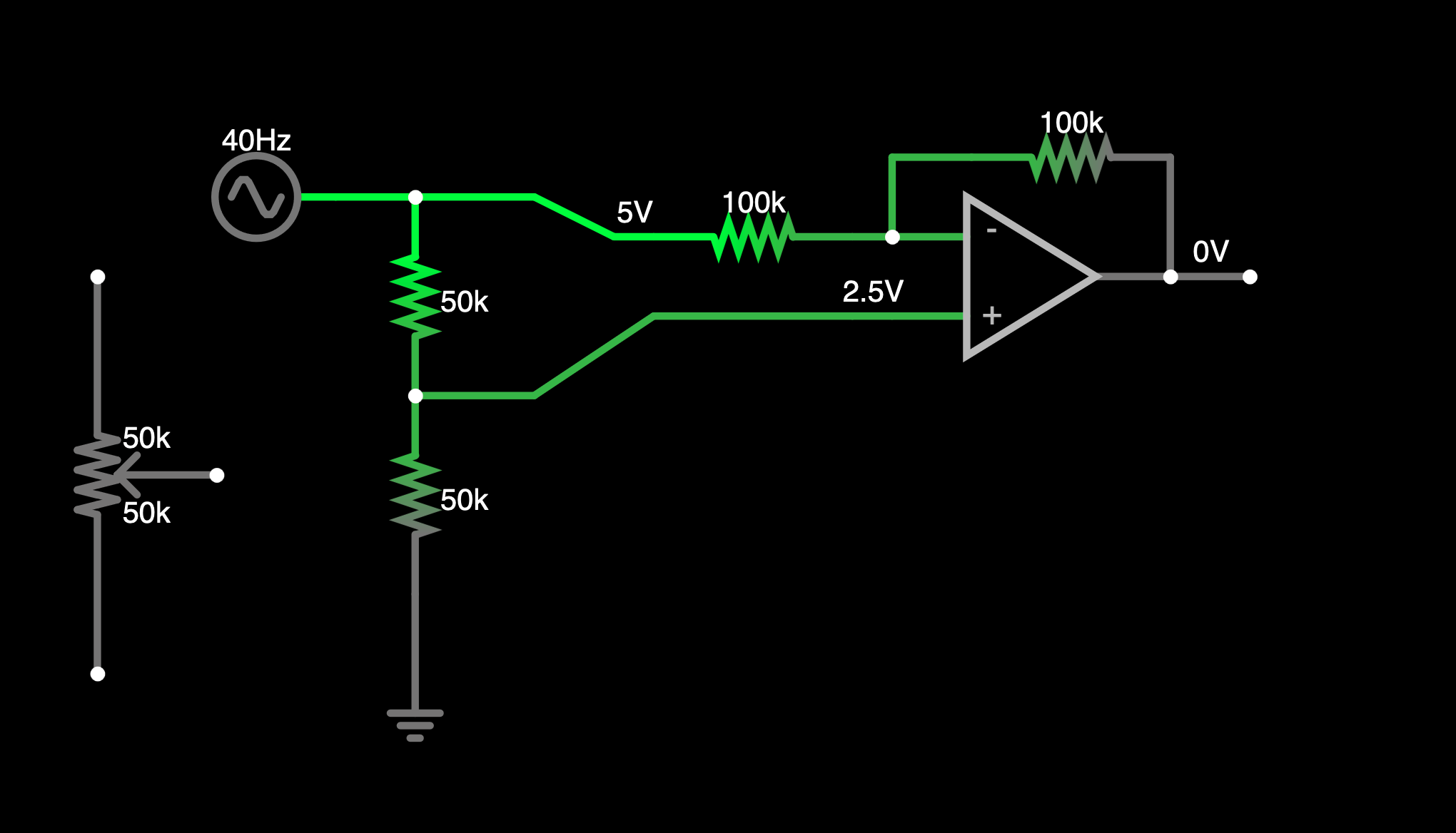
so now, the pot is acting as a voltage divider; the (+) opamp input is seeing +2.5V. The (-) input is seeing +5V. So what is the opamp going to push?
it has to push 0, because that feedback path is an averager, and if one side of the averager is +5, the result of the averager needs to be +2.5, then the other side of the averager has to be 0V:
its very smart, the entire thing uses very few parts, and works almost entirely through clever use of voltage dividers/averagers.
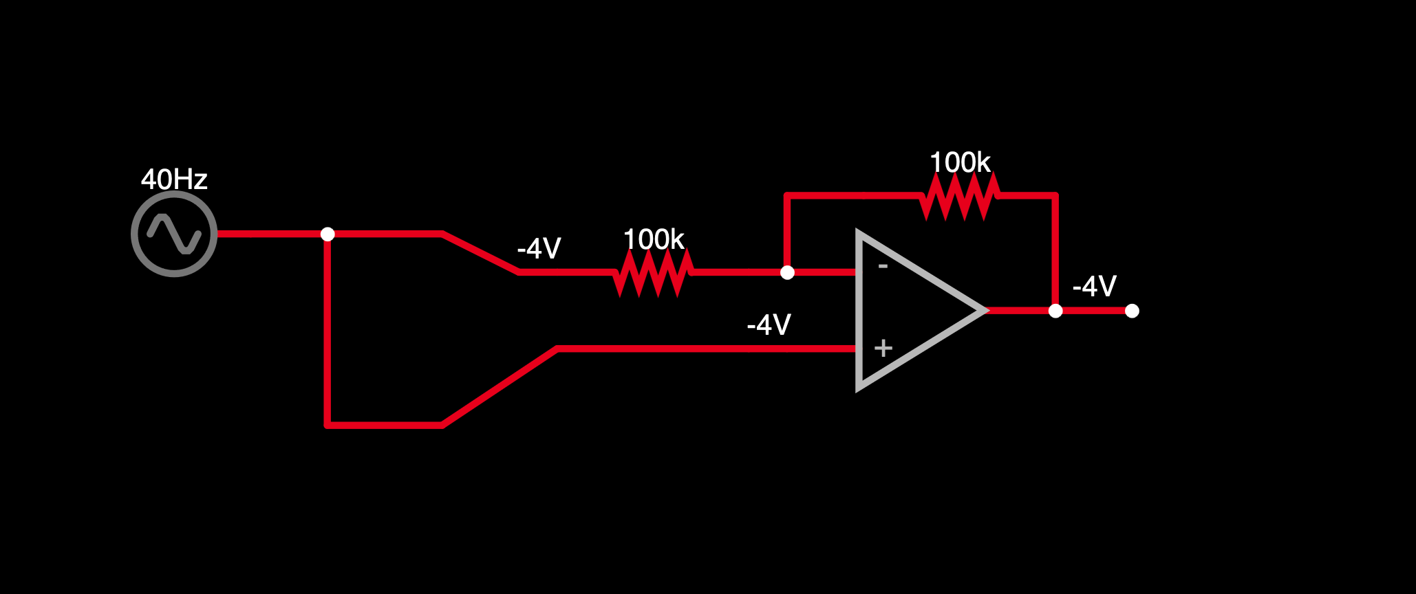
there's a maybe useful application here - it's possible to do a non-inverting amplifier that looks pretty much like the inverting one; all you have to do is connect the signal to the (+) opamp input instead of ground. if you are making a unity-gain version, there's probably not much point in using this as you can accomplish the same thing with no resistors, so for example you could do this but i'm not necessarily sure why you would:
 ... but it's worth remembering that we can use the attenuverter circuit pretty much anywhere we want to, and if what we're after is fixed attenuation instead of knob-controlled, we can just put in whatever R values we need to get the attenuation we want. So for example we can build something like this:
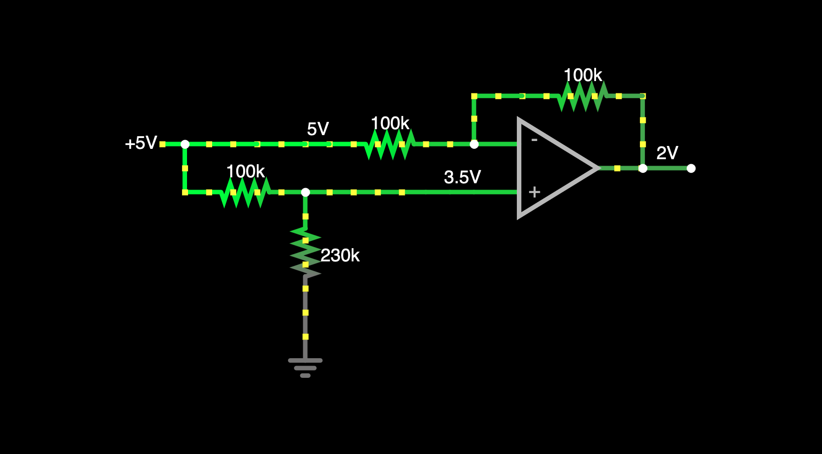 ... what is cool about this ^^ is we can attenuate through a single opamp without inverting/flipping the phase. it uses 4 resistors, yes, but only a single opamp - this is in contrast to the more sort of "normal" non-inverting opamp configuration, where the gain is always >= 1.
(and another advantage is i almost always use inverting configuration and i can never rembember the non-inverting configuration - unless it is unity gain - and always have to look it up).
so what R values do we need to use? (wip)
i think this is not really very different from a crossfader (wip)
the "precision" version (wip)
the befaco version (wip)
